Showing posts with label RapMan print. Show all posts

Tuesday, March 27, 2012

A Z-Axis Wobble Limiter Proposal

Once we have identified that we might have a Z-Axis wobble issue with .125 resolution prints, we need to decide is it's bad enough to worry about or not.

Z-Axis Wobble under a 40x Microscope

The reason I chose an extruded triangle for creating my test tower is that I knew it would form and sharp edge that would provide the best look at the wobble under a microscope.  I wasn't disappointed.  Now, remember, each layer is just .125mm high.  So, with this better image, I estimate the wobble is probably just between .25mm and .50mm.  That is not very much.

Pulled back a bit, we can see how shallow the wobble is in the case of my RapMan.  This image also shows that the wobble mirrors one turn of the threads of the threaded robs.  The pattern will always be the same length.  Only the depth of the pattern will change depending on how badly the threaded rods are bent.  This is so shallow that it probably represents a single rod, not all four.

Wider View of the Z-Axis Wobble Evidence


In my case, I really don't think it's a show-stopper.  However, this is a blog about 3D printing and that raises the bar on the level we need to expect for ourselves.  And, that is nothing less than the best prints that might be possible from a 3D printer.  Period.

That means addressing the problem if for no better reason than the general issue among all users needs to be addressed.

Z-Axis wobble is a well known issue for most 3D printers.  So, there are some very good solutions floating around in various 3D and RepRap forums.  There are even fixes that you can download to replace the default Z-Axis system that came with your RapMan.

There is one problem with each of these solutions.  They require taking your RapMan apart to replace the Z-Axis lifts on all four corners of the RapMan.

My goal, in pondering a solution was to find a way to minimize or eliminate wobble WITHOUT taking the RapMan apart.  I wanted to be able to continue the original RapMan system for raising and lowering the bed.  I have no clue if the solution I am proposing will work.  At the moment I have run out of filament and can't build and test the idea immediately.  But, I can describe the proposal.

Here is a rough image that, hopefully, explains what I am planning to try.  There is a LOT of design work yet to be done beyond this rough concept drawing.

Proposed System - Rough Outline
First, the blue section represents the original parts that hold the nuts that raise and lower the bed on the threaded rod.  You'll have to imagine the nuts and springs that comprise the lift mechanism.  The hole in the blue part represents the hole for the threaded rod.

Normally this plate would be directly connected to the bed frame.  But, in this case I'm proposing to put some parts between the lift plate and the bed frame.

The first of these is the bottom red part.  It bolts to the lift plate in place of the bed.  It has a fixture into which we will insert some spring steel (Grey in the above image) that can be obtained in any hobby store.  The optimal gauge and length we will need has yet to be determined.  It is this wire that will provide rigid support for vertical movement while dampening lateral movement.

The wire fits into a similar fixture in the underside of the top red piece.  It is locked into place with a set screw and/or appropriate glue.

It is the top fixture that isolates the wobble in the blue section.  Notice that the hole through which the threaded rod runs is larger in this fixture.  We do not want it to make contact with the threaded rod.  As I said, this is a rough approximation of the plan.  In the actual part, it will have to be made so that we do not have to remove anything.  So, the right side of this section will probably have to be in two parts.  And, the hole on the far right, which represents the hole for the smooth outside support rods will actually be two bearings.  Again, this is simply a rough concept.

The bed support will be bolted to the top red part.  This part will be isolated from the source of the Z-Axis wobble by the spring separating the top and bottom units.  And, the bed will be steadied by the top component's connection to the outside vertical support rods.

Hopefully, then, the spring will make a tight vertical connection while allowing the lower section to wobble without that wobble being transferred to the top section and bed support.

Until the replacement filament arrives, we won't know if this technique will work.  But, we do know that if it doesn't we have not altered the basic Z-Axis operation and can return to it fairly easily.

I'd love to hear ideas pro and con about this proposal.  Perhaps you have already tried something similar.  If so, please let me know.

What is RepRap & RapMan Z-Axis Wobble?

I'm fairly confident that any issues with the Y-Axis alignment and the Bed Leveling alignment on my RapMan has been successfully solved using the new tools that I designed to make the process more precise.

But, when printing at .125mm, it is apparent that one more issue may need to be tackled.  And, that is probably some issue with some relatively minor Z-Axis wobble.

This video isn't all that great.  The lighting is poor and the image is 640x480 because it was shot at 240fps so we could analyze the image in slow motion.  I'll try to get better images of all four threaded rods this evening.
However, it is still useful enough to use right now.


What this video shows is that if there is any wobble at all, it is very. very minor.  Yet, because we are working with such tiny tolerances, it is still noticeable in the printed output.  As the following samples show.

Here is the test object.  It's a tower having 3 equal sides.  This shape was chosen because it results in 3 sharp edges.  It was printed at .125mm resolution.  And, as you can see, there are some visible ridges that probably indicate Z-Axis wobble.

Test Tower
Looking at a crop of the image, we can see the ridges a bit more distinctly.

Test Tower - Crop showing ridges more clearly
By laying the tower on its side and angling the light to create shadows, the ridges become more identifiable.

Lighting to accentuate the ridges
While we can see an interesting pattern in the above picture, it's not so clear as to how many layers there are in the repeats of that pattern.  For that we need a microscope.  Again, the following picture was created using the worst microscope I have in my collection and the camera was hand held to the eyepiece.  So, it's not the best we can do.  Even so, it is helpful to see for this article.

Ridge pattern through a 20x microscope
The most important thing about this image, and something with which I want to follow up, is that the ridge pattern looks to be about 12 rows.  If 12 (or so) rows equates to a full turn of the Z-Axis threaded rods, we have evidence of Z-Axis wobble.  Yes, it's on a small scale.  The wobble appears to be less than .5mm.  But, it is there.  And, theoretically, we should be able to get that down to virtually zero.

In subsequent posts, we'll explore some of the solutions that other 3D printer users have come up with to deal with this issue.  But, before we leave this subject, it might be interesting to see what we are up against in dealing with the threads of the threaded rods.

Threaded Rob Up Close and Personal
If you click on the above image, you will see that threaded rods aren't always as cleanly threaded as we would like.  In fact, I don't believe I have ever seen a perfectly clean threaded rob.  This one is as good as any I've seen.  Yet, it clearly has some defects and/or debris that might affect the print.

While looking at the screw, it dawned on me that I should be able to place the test tower next to the threaded rob and take some macro images to see if the threads match the pattern of ridges.  I'm guessing they do.  :)


Sunday, March 25, 2012

Fine tuning RapMan 3.2 - Hot End clearance

The RapMan gives us several tools to raise and lower the hot end relative to the bed.

The first, and most basic, way to set the distance between the hot end and the bed is a long screw that hangs down from the extruder assembly.  Each time we select the bed height option on the console, the printer homes the machine so that this bolt can activate a switch and then the printer uses that position to move to the center of the bed and lower the hot end to the position called for the bolt's length.

The manual calls for adjusting the hot end so that it barely touches the bed.  "Barely" is the operative term.  I'd like something a little more measurable.  To get the most precise setting, I decided to use a mechanic's tappet gauge.  So, I started with the 0.102mm leaf on the mechanic's gauge to get the hot end as close as I am able to measure. But, through trial and error, I found that my particular printer responded best (laying down an undistorted raft) at 0.254 for PLA.

Here are the steps I use.
  1. Press the Z-Height Selection
  2. Make sure the Z-Height Offset is 0
  3. Try the 0.254 leaf of the gauge under the hot end.
  4. If there is a lot of clearance, tighten the adjustment bolt.
  5. If there is no clearance, loosen the adjustment bolt.
  6. Exit Z-Height adjustment

Repeat the above steps until the gauge just slips under the hot end.  Do NOT make changes to the Z-Height offset.  You are setting the base point and will use the offset to further fine tune for different situations or special cases.

I understand the critical nature of getting the hot end (Z-Axis) height right for the raft.  But, it's still unclear to me that it makes much of a difference in subsequent layers as the Z-Axis increments should take care of itself in spite of the starting height as long as the height was sufficient to create a starting raft.

And, the optimal height for any given printer with any given material might be a bit different.  That is because the setting you end up using is the setting that is able to lay down a nice raft without tearing it or distorting it.

The point is that we can get more precise in by using tools, like a mechanic's tappet gauge, we are better able to control our printing environment on a repeatable basis.

Fine Tuning RapMan 3.2 - Precise Bed Leveling

Making sure that the RapMan 3.2 bed is level is probably among the most important things we can do to ensure better results.

The build manual and the display panel gives up some tools to level the bed using three bolts.

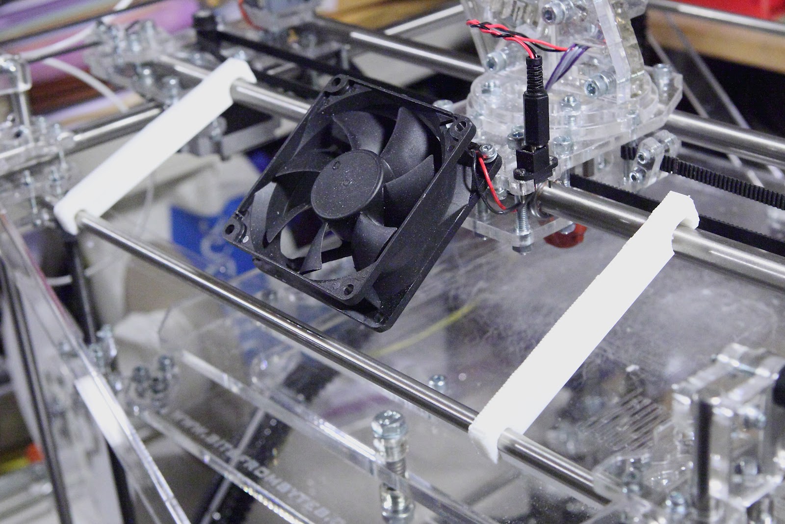
But, my eyes were having a hard time seeing the hot end height.  So, I decided to make some tools to help me do this more precisely.  First, I bought a set of mechanic's valve tappet gauges.  Using a gauge under the tool that I am going to describe is the most precise way to ensure that all points are even.

First the tools...

Bed Level Tools

 Basically, these two tools are hung over the X-Carrier rails and hang down.  The four points are an even length.  Here is how they are used.

Tools hung over at each end of the X-Carrier rails.

Notice that that a tappet gauge is being slipped under one of the pointed rods.  Adjust the height of the bed using the console until the gauge can be just slipped under the point.  It should NOT lift the tool.  Now, by simply using the bed leveling bolts, ensure that the gauge just slips under each of the other points.

Do this front and back.

Gauge being used at the back of the bed
These tools are a LOT easier to see than the tip of the hot end because you can place them so close to the edges of the adjustable bed assembly.  You can get up close and personal.

Finally, I had created an earlier set of alignment tools designed to do the same thing.  However, these sat on the bed, itself and had clips similar to those of the X/Y Carrier alignment tools.  I now use these just to verify that the bed is level.

Verifying that the bed is level


The latter step  is not really required.  I simply have the posts already and it's a good tactile way to verify that the bed is level.  Raise or lower the bed until one of the tools clips easily on the carrier rod and the other tool should also clip easily.

Once bed leveling is complete, we need to adjust the hot end height.  And, for that I also use the mechanic's tappet gauge.

Fine Tuning the RapMan 3.2 - X Carrier Alignment

So far, I have not found a single defect in the design of the RapMan 3.2 that I could pinpoint for you.

However, the printer is only going to print as well as we have built our RapMan printer.  And, I am determined that I am not going to be content until I have assured myself that the printer I have built is as good as any other RapMan out there.  And, that means finding ways to fine tune as many of the variables as I can.  And, at least for me, this means a By-The-Numbers approach to alignment.

Fortunately, the RapMan can help us out here, by allowing us to build alignment tools that we can use to ensure that we are as close to the most precise tolerances as we can get.  I want to talk about some that I've created for myself.

The first is a tool that allows me to align the Y-Axis travel.  The RapMan uses two belts for the Y axis.  And, it's possible that these two belts are pulling at an angle.  The best way to ensure that both belts are adjusted so that the X-Carrier is in perfect alignment is to measure the distance on both the left and the right sides to make sure they are equal.

Here is the alignment tool that I built for this job.  We use two.

Y-Axis Alignment tool
Notice that these alignment tools have a small half circle and a large half circle.  The small half circle fits over the top front rail and the large half circle fits over the front carrier bar for the X-Y carriage.  Clip the tool on the front rod and move the X-Y carriage carefully until it's possible to easily clip the tool onto the first rail of the carriage.  Do NOT force it.  Here is what it looks like.

Left Side Y-Axis Tool Attached
Then clip the other alignment tool to the front rod and ease it down to the carrier rail.  Again, do NOT force it.

2nd Alignment tool attached to front rail

Alignment tool being lowered to carrier rail

If the 2nd alignment tool will not easily clip onto the carrier rail, then the carrier is out of alignment.  Loosen the Y-Axis pulley at the back right of the printer and pull or push the right end of the carrier until the tool can easily be clipped to the carrier.

Carrier aligned
Then tighten the pulley.  The carrier should now be aligned.  But, you may want to remove the alignment clips and try the steps again to ensure that the X-Carrier is, indeed, permanently in alignment.


Tuesday, March 20, 2012

RapMan 3.2 Unattended Print at .250mm

UPDATE:  I did manage to figure out why the .125mm test was not, initially. printing well.  It didn't dawn on me that because the layers were 1/2 the thickness, I needed to raise the bed to compensate.  Once that was done, it was running fine when I left it this morning.  Hopefully, it completed the job.  I'll find out in an hour or so.  I HATE DC area traffic!  LOL!

Before leaving for home... and hopefully finding a higher resolution print of Peyton Duncan's Chow waiting for me... I managed to capture some better images of the printed model from my RapMan 3.2 printer.

Nobody is trying to fool anybody.  An extrusion printer doesn't cost $400,000.  Neither does it perform like one.  But, it still does a very credible job at rendering what one creates.  And, frankly, I'm quite pleased with the result at .250 vertical resolution.  So, here are some images.

NOTE:  Any lint, etc. comes from the fact that this poor guy spent all day in my pocket.  :)

Click on any image to see larger versions... 

Peyton Duncan - Chow View #1:  .250mm

Peyton Duncan - Chow View #2:  .250mm

Peyton Duncan - Chow View #3:  .250mm

Peyton Duncan - Chow View #4:  .250mm

Peyton Duncan - Chow View #5:  .250mm

For these next two images, which only appear to be identical, I raised the F-Stop for each to try to get a bit more depth of field.  I think it helped.

Peyton Duncan - Chow View #6:  .250mm f16.0

Peyton Duncan - Chow View #7:  .250mm f18.0
As you can see, the RapMan, once properly set up, begins to crank out some very nice 3D prints!  And, that is even at the Mid-resolution.

Note for Peyton...  I KNOW that is a DIME in the image and not a quarter as you asked.  How in the world did you think I might have a quarter to my name left while I'm spending all my money having fun buying tools and materials for my RapMan???   LOL!

Note for everyone else...  Peyton is my nephew.  And, I have a LOT of respect for his work and for him personally.  Both Peyton and my artist daughter Cheryl continue to amaze me with their talent. Here is just a sample of Cheryl's beautiful sculpture that got me interested into digital photography and  3D printing in the first place.

Fleurette by Cheryl Meeks


I'm surrounded by geniuses and loving it!

Now... I gotta get out of here to see what awaits me at home... a mess or a Chow!!  :)